
Most surviving TR-1s no longer work. Many collectors (such as myself) prefer to keep them in "as-manufactured" condition. That way the authenticity is preserved. But at some point, you may be anxious to hear one play. Before you start soldering, ask one question -- DO I REALLY WANT TO DO THIS? Once it's changed, it's no longer original, and you may end up with a "modified" radio, and still have one that doesn't work!
NOTE -- I'm presenting the information below to document what I did. Unfortunately I'm really not in a position to fix radios belonging to others. There are people who do specialize in fixing "antique" and collector radios and you should be able to track some down on the web or in newsgroups. But unless you have significant experience with electronics repair, I would think carefully about doing it yourself.
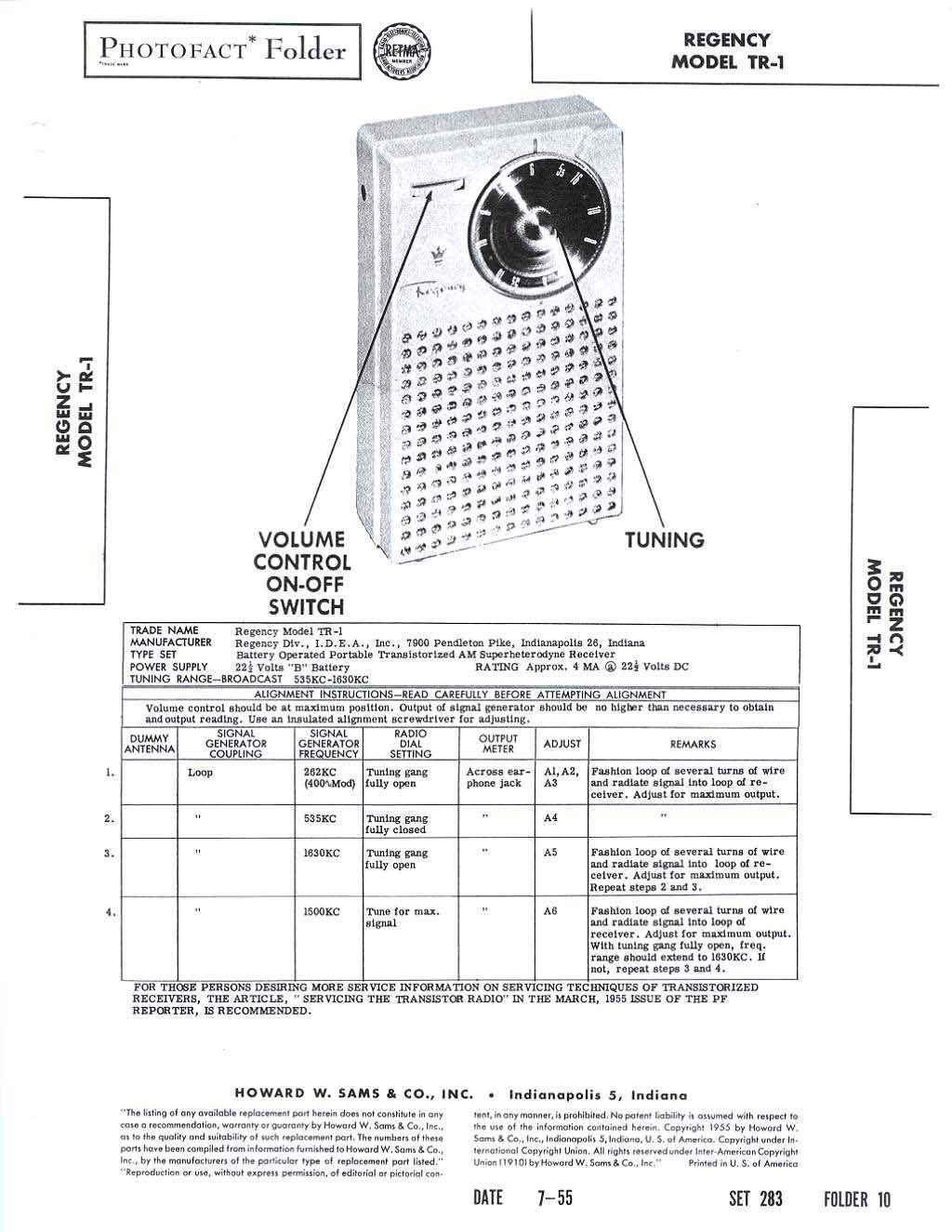
Getting Started
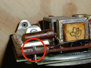
When I bought my ivory TR-1, I discovered that it had been modified. So I figured, "well, it's not authentic anymore anyway, so now I've got my 'experimenter' radio". The first clue was when I spotted a replacement oscillator/converter transistor, X1. The "new" one was a GE 2N168A, which dates back pretty far. It "wiggled" when I touched it -- a bad sign, indicating the foil PC board trace into which it was soldered was probably pulled away from the board. This happens when too much heat is used in soldering.
Collecting Documentation
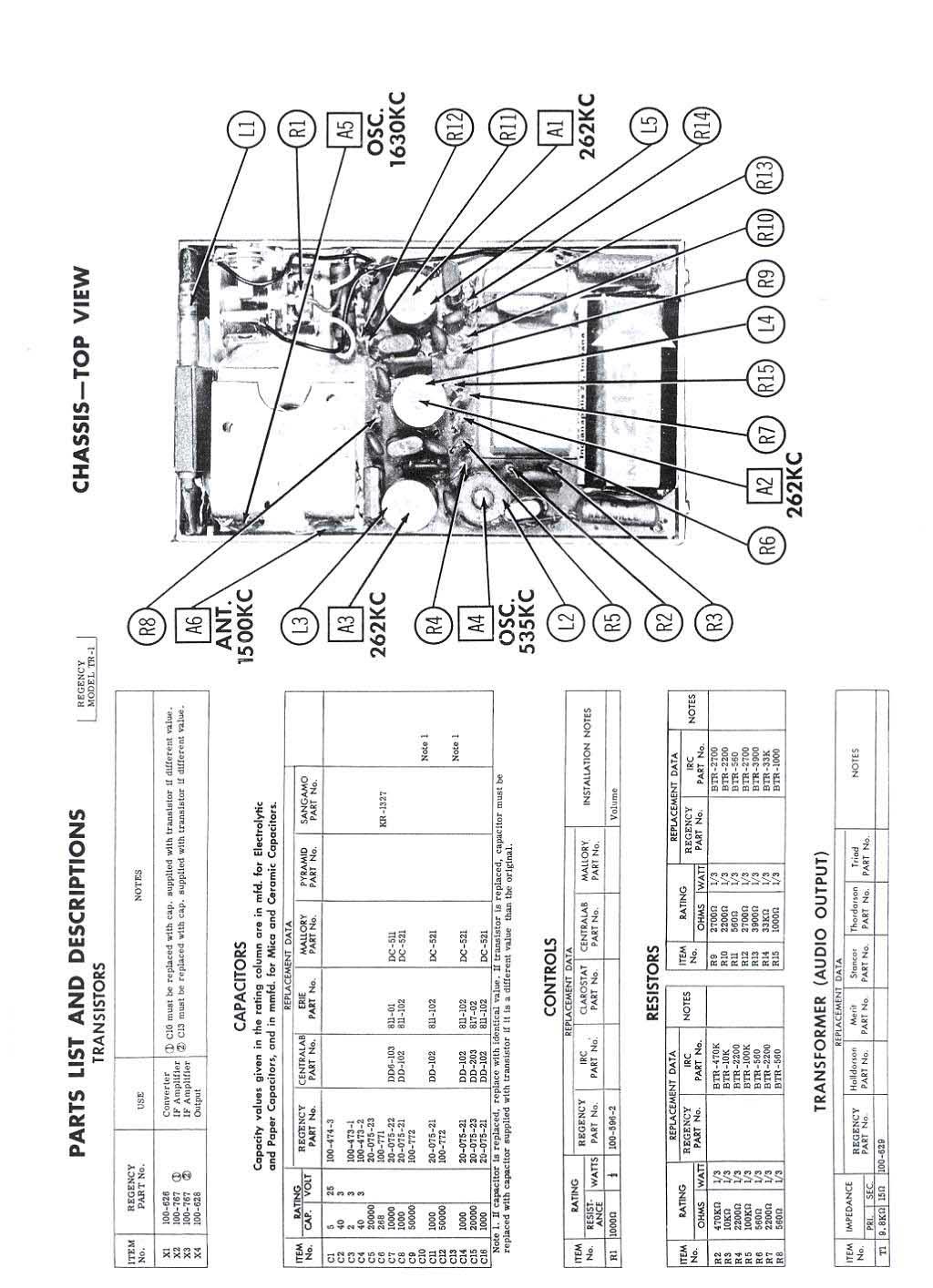
I was going to need good documentation of how the radio should appear, where the
parts go, and suggested schemes for doing the repair. Here's what I used:
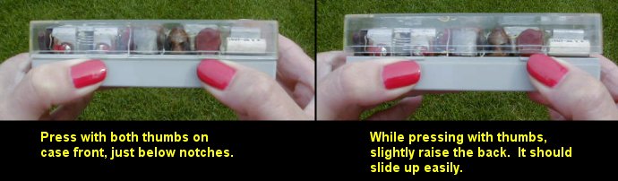
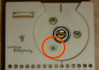
Taking the Radio Apart
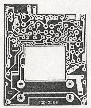
Now comes the next major decision. Should the PC board be unsoldered from the chassis? Many parts, including the commonly-defective electrolytic capacitors, can be replaced without unsoldering the board, and for that matter, without unsoldering the part, if you're careful. To replace an electrolytic cap, you could just clip the leads of the old one and solder the new one to those leads. The result is not as "pretty" as actually replacing the cap on the board, but it may be less risky. But, if you need to remove the board ...
Making the Repairs
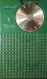
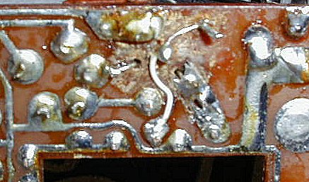
You can see the damage on the foil side of my PC board. I cleaned that up and replaced some traces with 30 gauge wire-wrap wire. Note that someone had substituted a green wire for a damaged trace.
The repairs to be made to the circuit depend on what's wrong, and following the PF Reporter article should track things down. My own feeling is that the likely culprits are probably the electrolytic capacitors. I found two of my four to be shorted, one open circuited, and the other one working properly. I replaced all four. The exact values are not too critical. For example, I replaced them as follows: 5uF/25V and 2uF/3V each with new 4.7uF/50V. And the two 40uF/3V with new 47uF/25V. Pay close attention to the polarities before removing the old ones.
I also discovered the on-off switch to be bad. This is just two pieces of metal that touch, so I took a screwdriver and used the edge of it to scrape away any dirt from the contacting parts of the switch. That fixed it. I also bent the battery clip a little tighter, and cleaned the "switch" contacts in the earphone jack.
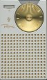
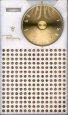
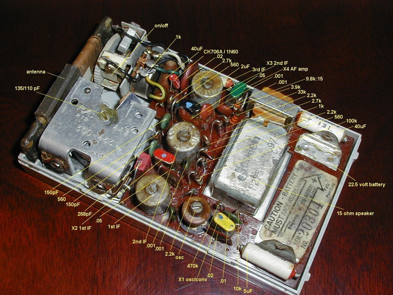
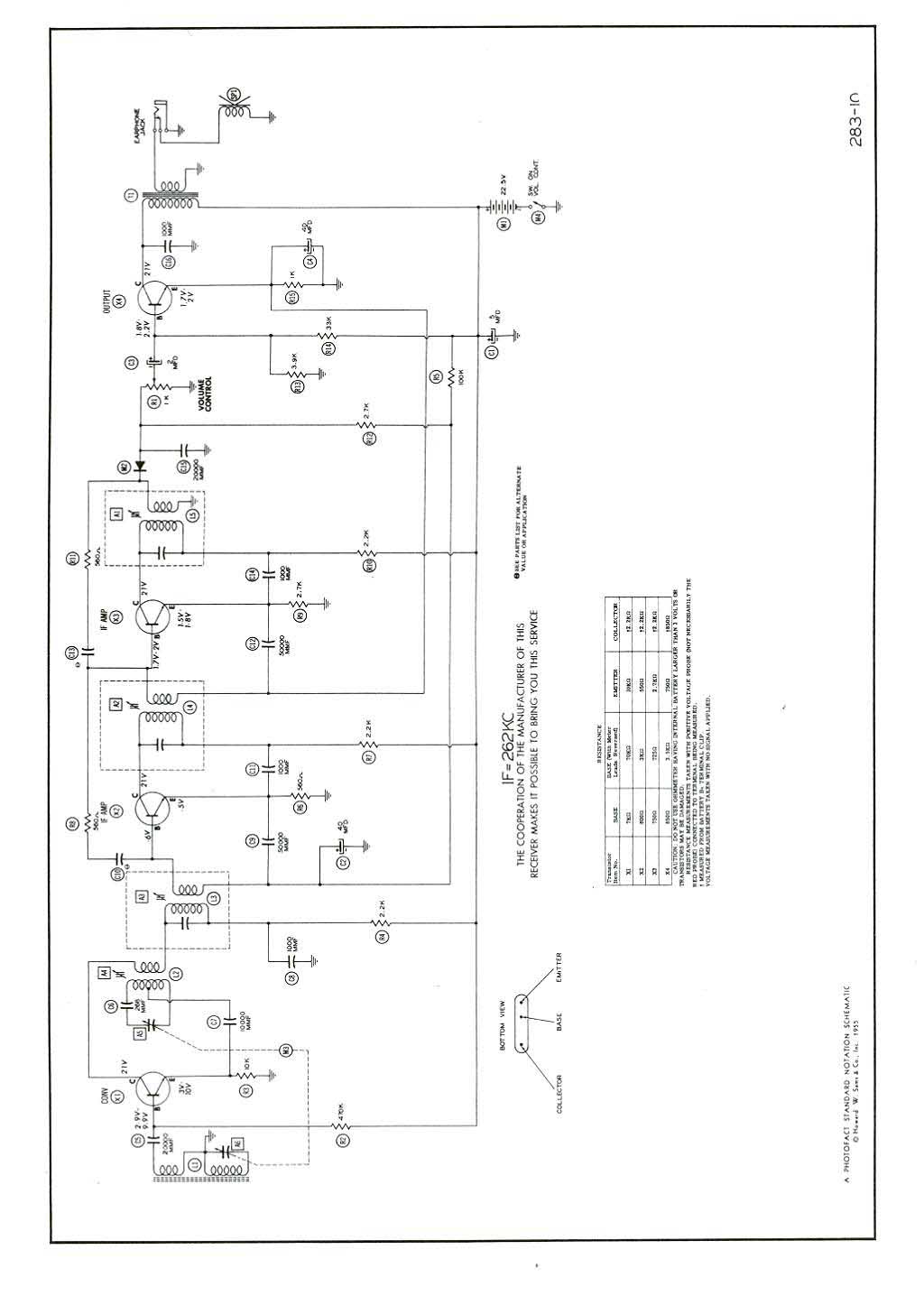
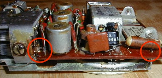
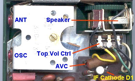
There are various important test points in the radio. The photo shows connections to the AVC (Automatic Volume Control) line, IF (262 kHz Intermediate Frequency) signal, and audio before and after the AF (Audio Frequency amplifier) stage (at the top of the volume control, and at the speaker, respectively). The ANT and OSC trimmers are shown as I believe they are configured. The various coils are not shown, but the one without the metal can is the oscillator coil, and the others are the IF transformers.
Now, when it's fixed, put it back together. Be careful soldering the tabs between the chassis and the board -- it's easy to create solder bridges.
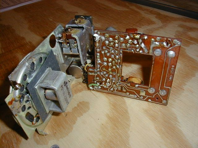
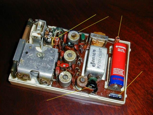
While it's possible for other parts to be bad, it's probably less likely. However, if "re-capping" the radio doesn't fix it, then the troubleshooting article should help. Here's what the radio looked like after I was finished. The yellow lines point to the new capacitors, and to somebody's replacement transistor (some time later I replaced that transistor with an original TI223).
The current draw is roughly an average of 4 mA at 22.5 volts. A test with a dc voltage source shows it operates well even at voltages as low as 15 volts. That's good news as far as battery life is concerned.
Alignment
I experimented by making slight adjustments to the cores in the IF transformers and oscillator coil, and adjusting the trimmer screws on the tuning capacitor. It was aligned fairly well to begin with, but the dial calibration was off by about 30 kHz. There is some risk in turning the cores in the coils -- you could break the ferrite material. Another problem I found in tuning the oscillator coil was that the COIL turned instead of the core. If I had turned it any farther I may have broken the delicate leads connecting the coil to the base. A little dab of instant glue solved that problem and allowed the alignment to continue (I followed the procedure in the PF Reporter article). Using instrumentation I found the center of the IF amplifier to be around 273 kHz rather than 262. This is not a big problem (it's a somewhat arbitrary choice) and I could have left it, but I decided to adjust it to exactly 262 kHz for the sake of authenticity. Did the alignment help the sensitivity? Not sure, but I like to think so.
How Well Does It Work?
After reading the Consumer Reports article, I was fearful of bad performance. I was pleasantly surprised at what I discovered. The radio has a "full" sound; not tinny like some transistor radios, and has plenty of volume. I recorded some off-air signals for you to listen to. I put a (cheap) microphone in front of the speaker and captured the audio with a laptop computer as a WAV file, and then compressed it to MP3. This grand experiment was performed in my family room and so the radio got some interference from the laptop and from the DSS satellite receiver about 15 feet away.
I live in suburban Milwaukee, Wisconsin, about 15 miles north of the middle of the city.
The radio was oriented so the maximum sensitivity was to the south, toward Milwaukee
and Chicago (approx. 100 miles away). I easily heard stations from both cities.
Tests 1 and 2 were performed at about 8:30 PM, on Dec. 22, 2000, prior to
aligining the radio.
TEST 1 -- WOKY - 920 kHz, Milwaukee (70kB, 17 seconds, MP3)
TEST 2 -- For this, I tuned the radio gradually through the
whole AM broadcast band,
from 540 kHz to 1610 kHz. It picked up various stations from Milwaukee and Chicago
(289kB, 73 seconds, MP3). The graph shows the audio amplitude as measured at the microphone.
|
 |
TEST 3 -- WOKY - 920 kHz, Milwaukee, 6:30 PM, 12/23/00 (212kB, 26 seconds, MP3). For this test, the earphone jack was directly patched into the laptop's sound card, so the
fidelity is not affected by the microphone. As can be heard, the audio is clearer, and has
better high frequency response. The volume control was set near minimum. On some stations,
with certain program material, at certain volume levels, some distortion was noted.
With the patch cord used, the TR-1's audio stage was probably not terminated in the same
impedance as the earphone (would have presented) so this could affect the results.
This, too, was performed prior to alignment. All in all,
though, the sound was pleasing, especially considering the early, groundbreaking design.
I'd say "congratulations" Regency! You started it all!
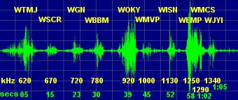
TEST 4 -- "Working some DX" (long-distance stations) (298kB, 37 seconds, MP3).
On 2/10/01, from 7:00-8:30 PM, I recorded signals from some distant stations. They are spliced
together here, and show impressive sensitivity. This test was run after I had aligned my ivory TR-1.
The alignment seemed to help the sensitivity, making it fairly "hot".
The callsigns, frequencies, and approximate distances are:
|
TEST 5 -- Lab Generated Signal (178kB, 2 seconds, WAV
- in case you want to experiment with the data).
A synthesized modulated signal generator (Hewlett-Packard 33120A)
was used to apply a 740 kHz signal, with 400 Hz, 50% modulation, to a small wire loop positioned near the
TR-1's loopstick antenna. No broadcast band
signal was close to this frequency, the nearest being at 720 and 780 kHz, around 100 miles away.
A moderate strength signal was applied, causing the AVC
voltage to change from approximately 0.50 with no signal, to 0.15 with this signal applied.
A strong signal drives the AVC voltage to nearly 0.00. There was some hiss in the resulting
audio, due to the lack of signal strength.
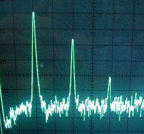
The oscilloscope plot (left) shows the RF, the 262 kHz IF, and the audio signal (across the speaker, which was in the circuit). Even by eye, the audio appears distorted. A spectrum analyzer plot (right) shows significant components at 400, 800 and 1200 Hz with amplitudes of +1, -16, and -41 dB. This yields a total harmonic distortion (THD, calculated as a ratio of RMS distortion to RMS fundamental levels) of 13%. The level of quality of the signal generator would seem to imply that the distortion is truly caused internal to the TR-1. Further investigation showed that about half of the distortion is present before the audio amplifier stage (at the top of the volume control), with the remaining half being produced by the audio stage itself. The AVC voltage has about 1 mV of audio on it (on top of the 150 mV AVC level), but this slight unwanted feedback does not appear to account for the distortion being created (additional AVC filtering did not affect the distortion). The distortion at the speaker with 100% modulation was almost 27%.
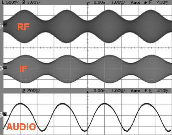
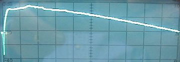
The spectrum analyzer's tracking oscillator was then used to modulate the signal generator, with the spectrum analyzer plotting the response of the radio. The following frequency response plot shows the range from zero to 10 kHz, with a 10 dB/division vertical axis. The response is fairly flat from 250 Hz out to about 5 kHz.
Conclusions
I had read-up on the repair process ahead of time, so it would go smoother. When I finally started the work, the whole process took under two hours. There's always a certain amount of both skill and luck involved in troubleshooting, and experience helps, to be sure. I really never thought I'd hear a TR-1 play, but when the ivory one turned up "defiled", I knew it was my chance. To hear music come from the radio, through those primitive transistors and Richard Koch's original circuit, is thrilling. It was the first. Thanks Regency! If you try the repairs too, I hope it goes well.
 These web pages on the Regency TR-1 were created and updated for many years by Dr. Steve Reyer, who passed away in 2018. He was a true enthusiast in the radio hobby and is greatly missed. Steve was Professor Emeritus (Electrical Engineering) at the Milwaukee School of Engineering. He earned his Ph.D. in electrical engineering at Marquette University. Steve had hobby interests in consumer electronics and in Milwaukee Architecture. We are honored to keep his extensive efforts in the hobby alive and available here at collectornet.net
Copyright © 2019-2021 collectornet.net